Services on Demand
Journal
Article
Indicators
-
 Cited by SciELO
 -
 Access statistics
Related links
-
 Cited by Google
 -
 Similars in
SciELO
 -
 Similars in Google
Share
Revista Facultad de Ingeniería Universidad de Antioquia
Print version ISSN 0120-6230On-line version ISSN 2422-2844
Rev.fac.ing.univ. Antioquia no.51 Medellín Jan./March 2010
Use of the information gathered during I/M programs to estimate emissions from gasoline vehicles
Uso de la información recolectada durante los programas de I/M para estimar emisiones de vehículos a gasolina
José Ignacio Huertas1, Efrén Mendoza1, Jorge Córdoba2
1Centro de Investigación en Mecatrónica Automotriz- CIMA. Tecnológico Monterrey. Eduardo Monroy Cárdenas No 2000, San Antonio Buenavista, Toluca, México 50110
2Universidad de Antioquia, Apartado Aéreo 1226, Medellín, Colombia
Abstract
Currently, most of the vehicular emissions inventories developed for large cities are based on the emissions factors developed by the US EPA. Trying to use the US EPA MOBILE tool, the local environmental authorities concentrate their efforts in modifying those emissions factors to take care of the particular characteristics of each city. However, there is still a need for a methodology based on experimental tests to improve the accuracy of the emission inventories developed for large cities. To address this need, the present work proposes a methodology to improve the accuracy of the vehicular emissions inventory using the information gathered during the inspection and maintenance (I/M) programs where the emissions of 100% of the vehicular fleet is evaluated using the ASM 5015, ASM 2525 or similar type of tests. Experimental work on road and on a chassis dynamometer was developed to explore the feasibility of implementing such methodology for the case of the constant speed mode of operation in a particular type of car. Preliminary results show that the proposed methodology has the potential to be implemented for the case of constant speed mode of operation.
Keywords: Emission factors, exhaust gas emissions, I/M programs
Resumen
Actualmente, la mayoría de los inventarios de emisiones realizados para los grandes centros urbanos están basados en los factores de emisión recomendados por la US EPA. Buscando usar la herramienta MOBILE de esta agencia, las autoridades ambientales concentran su esfuerzo en modificar esos factores de emisión para que tomen en cuenta las características particulares de cada ciudad. Sin embargo, aun permanece la necesidad de una metodología que basada en datos experimentales mejore la precisión de los inventarios de emisiones realizados para los grandes centros urbanos. Para atender esta necesidad, el presente trabajo propone una metodología que se basa en la información recolectada en los programas de inspección y mantenimiento (I/M) donde el 100% de la flota vehicular es evaluada usando los protocolo de pruebas ASM 5015, ASM 2525 o similares. Se realizó trabajo experimental en pista y sobre dinamómetro de chasis para explorar la posibilidad de implementar la metodología propuesta para el caso de un vehículo operando a condiciones de estado estable. Los resultados experimentales muestran que la metodología propuesta tiene el potencial de ser implementada para el caso de velocidad constante.
Palabras clave: Factores de emisión, emisiones vehiculares, programas de inspección y mantenimiento
Introduction
It has been found that mobile sources are the main contributors to the air pollution in large cities such as Mexico, Bogotá and Sao Paulo [1,2]. These conclusions arise from studies of emissions inventories that are based on the emissions factors developed by the US EPA and the use of the US EPA MOBILE methodology [3,4]. A great deal of effort is spent finding estimates of modifying emission factors that allow to account for the particular characteristics of the city in terms of fuel type, technical specification of the vehicular fleet, driving habits of the citizens, and the governmental programs implemented to control the vehicular emissions. However, in most of the cases, those efforts are limited to analytical approximations. Therefore, there is still a need for a standard methodology, based on experimental tests, that allows improving the accuracy of the emissions inventories developed for large cities, either by modifying the US emissions factors or by proposing new ones. To address this need, the present work proposes to use the information gathered during the inspection and maintenance programs (I/M programs) implemented in most of the large cities, where the emissions of 100% of the vehicular fleet is evaluated using the ASM 5015, ASM 2525 or similar type of tests [5,6].
The emissions factors are the average amount of pollutants emitted by a type of vehicle when a sample of that type of vehicles follow the typical driving cycle of the city. They are expressed in terms of mass of pollutant emitted per unit of distance traveled or per unit of fuel consumed. This definition represents two challenges for the environmental authorities. To obtain the typical driving cycle of the city and to test the emissions of a large number of vehicles following standard procedures and using extremely expensive equipment. Several works have been developed to address the first challenge of finding the typical driving cycle for each city [7,8,9]. Even though there are still some issues unresolved, it can be said that there are methodologies to obtain typical driving cycles at reasonable costs.
On the other hand, the inspection and maintenance programs implemented in most of the large cities as a measure to control vehicular emissions look for testing the emissions levels of 100% of the vehicles that move around the city. In some cases the emissions levels are verified using the ASM 5015, ASM 2525 or similar types of standard tests, which are dynamic tests and involve the use of a chassis dynamometer. Therefore here it is proposed to develop fundamental work that allows using the information gathered during the vehicular emissions inspection program to modify the emissions factors and therefore to obtain more accurate vehicular emissions inventories.
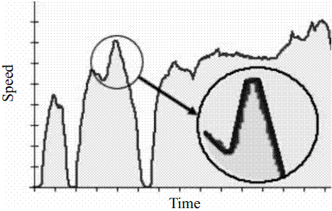
Any driving cycle can be approximated by a set of segments of operational modes. As an example, figure 1 shows a driving cycle and illustrates its approximation by segment of different operational modes. Initially the operational modes being considered are idle, constant velocity, constant acceleration and constant des-acceleration on roads without any slope. Assuming that for a given type of vehicle there exist functions fj’s that estimate the mass emission of a given pollutant as a function of the variable that describes each operational mode, the total mass emitted by the vehicle when it follows the driving cycle is:
Where
mi Mass of pollutant i emitted when the vehicle follows the driving cycle
fij Function that estimate the mass flow rate emission of pollutant i when the vehicle operates under mode j
vjk Value that describes the mode of operation j at segment k
Dtk Elapsed time of segment k
Figure 1 Driving cycle and its approximation by segments of different operational modes
Fundamental work has to be developed to obtain the general shape of the functions fij’s that estimate the mass emission of a given pollutant for each operational mode and for each type of vehicle. Car manufactures will provide these functions once a standard methodology to obtain them will be established by the environmental authorities. It is expected that, within the same type of vehicle, these functions will change depending on the age of the vehicle and other particular conditions of use. However the general shape of these functions will remain and the results of the dynamic test, performed for each vehicle during the development of the I/M program, can be used to calibrate or to obtain the exact functions, for each particular vehicle. Finally, the information gathered by all vehicular verification centers needs to be consolidated to obtain the emissions inventory. Currently, most of the environmental authorities of large cities collect the information gathered by all its authorized verification centers.
Implementation of the proposed methodology for the case of constant speed mode of operation
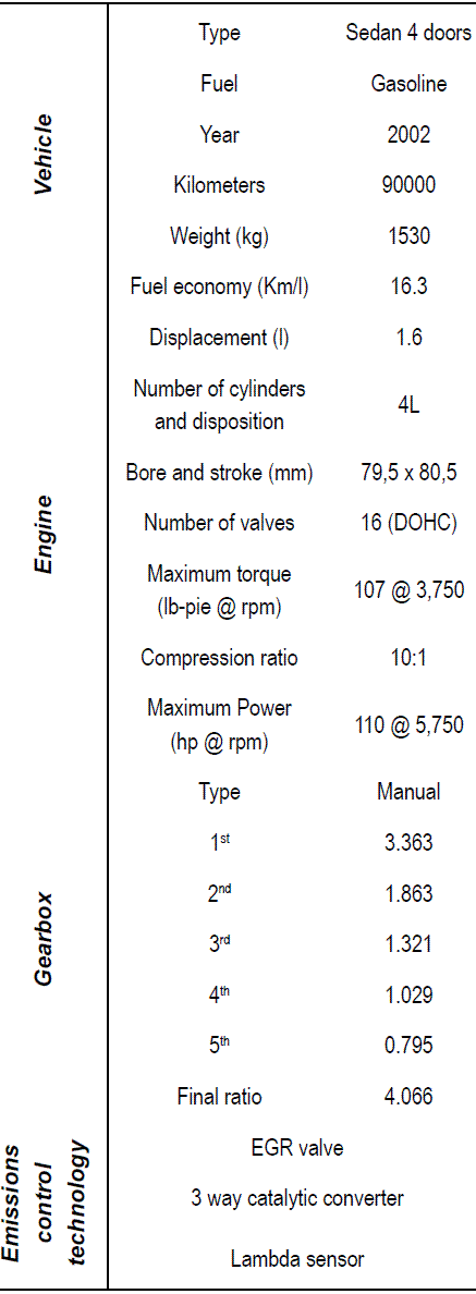
To explore the feasibility of implementing the methodology described above, for the case of constant speed operational mode, a set of experimental tests were conducted in a gasoline fueled sedan type vehicle. In the following section the technical specification of the vehicle, the instrumentation used, the test performed and the main results obtained are described.
Vehicle
Table 1 shows the relevant technical specifications of the vehicle used in this work.
Fuel and environmental conditions
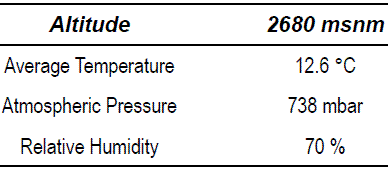
All the tests were performed using regular gasoline with the specifications described in table 2. Table 3 shows the average values of the meteorological conditions present during the development of the tests.
Table 1 Technical specifications of the vehicle used to evaluate the feasibility of implementing the proposed methodology [10]
Table 2 Gasoline used during the tests [11]
Table 3 Mean environmental conditions of the area where the tests were conducted [12]
On board instrumentation
The vehicle was instrumented similarly to reference 13. A fifth wheel was used to register the distance traveled, speed and acceleration of the vehicle. Reference 14 describes the technical characteristics of this instrument. The fifth wheel was calibrated following the manufacturer instructions. To monitor the loads imposed to the engine the signals registered by the Engine Speed (RPM), Throttle Position Sensor (TPS) and Manifold Absolute Pressure (MAP) sensors were acquired. Again these sensors were calibrated. Additionally, the fuel consumption was monitored by registering the injector pulse frequency and the time duration of each pulse injection. Equation 2 was used to calculate fuel consumption as function of these two parameters.
 P Pressure difference between the injector and the manifold at the moment of injection
ρ Fuel density
A Cross sectional area of the injector
C Discharge coefficient
f Injector pulse frequency
Dt Time duration of each pulse injection
n number of cylinders
 P was obtained by measuring gauge pressure at the injector’s common rail. A and C were obtained directly from the car’s manufacturer. f and Dt were obtained using and standard oscilloscope. Exhaust gas emissions were monitored using a standard, portable, five gases analyzer. Table 4 describes the technical specification of the gas analyzer.
Table 4 Technical specifications of the gas analyzer used in this work
The analyzer’s probe was adapted to the vehicle tailpipe using a stainless steel extension tube. A Pitot tube and temperature sensor were also adapted to the extension tube. Equation 3 was used to obtain the instantaneous pollutants mass emissions from the data obtained with the gas analyzer, the Pitot tube and the temperature sensor.
Where:
 Mass flow of pollutant i
r Density of the combustion products mixture
V velocity of the exhaust gases
A Cross sectional area of the exhaust gas pipe
Ci Mass fraction of pollutant i in the exhaust gases mixture
To estimate each of these variables the following global reaction was considered:
Where:
x Equivalent number of carbons of the fuel
y Equivalent number of hydrogen of the fuel
a Stoichometric coefficient
b1…b6 Number of moles of each byproduct
(l-1) Percentage of excess air
x and y coefficients define the equivalent gasoline composition. In this case it was taken as C8H15 [15]. a is obtained balancing equation 4 for stoichometric conditions, l and b’s are unknown. They can be calculated solving simultaneously the mass conservation equations for C, H2, O2 and N2 and the dry gas measurements for CO, O2 and NO provided by the gas analyzer. Then, the molar fraction (yi) of each species in the products can be calculated as
Then, the molecular weight of the exhaust gas mixture (M) is calculated from the molecular weight of the each species (Mi) as
Finally the mass fraction of each species is calculated as:
The density of the exhaust gases mixture (r) is calculated using the ideal gases equation with the following gas constant (R), where Ro is universal gas constant.
Finally, the velocity of the exhaust gases (V) is calculated as:
Where:
 P pressure difference measured in the Pitot tube
K Pitot tube calibration factor
Laboratory instrumentation
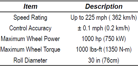
Laboratory tests were carried out on an electromagnetic chassis dynamometer described on table 5. The dynamometer was calibrated prior to each set of tests.
Table 5 Chassis dynamometer technical specifications
On road tests
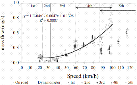
The purpose of the on road tests was to determine the mass emissions of pollutants and the engine operational conditions when the vehicle is driven at constant speed on a flat surface. It was made sure that the engine reached its normal operating temperature prior to the start of each test. TPS, MAP and RPM sensors were monitored for different constant speeds. Figure 2 shows the results obtained for the case of NOx mass emissions. Similar results were obtained for CO and CO2.
Figure 2 Comparison of the results obtained during the on road tests and the ones obtained on the chassis dynamometer for the case of NOx mass emissions under steady state conditions
As expected NOx mass emissions increase with speed and decrease at every change of gear. It is also observed a significant dispersion of the data. However this dispersion can be due to normal changes in the external variables such as changes in the atmospheric conditions and the presence of small slopes on the road. Therefore the present analysis should include the presence of such dispersion. Since the present methodology look for predicting the pollutant emissions of the vehicle starting from information gathered on a chassis dynometer, it is necessary to record the parameters that characterize the load requested to the engine during the constant speed on road tests and then impose the same load to the engine when the vehicle is being tested on the chassis dynometer. It was assumed that the engine load can be characterized by the RPM, % TPS and MAP variables. Usually, engine mapping performance is presented as torque or power output versus engine speed curves at full load. However different torque values can be obtained for a single RPM value, depending on the load imposed to the engine. Under normal on road conditions, the engine is partially loaded most of the time. TPS sensor is an indicator of the load that vehicle’s user is demanding to the engine. MAP sensor also indicates the engine load as it indicates the intake air flow to the engine, which is proportional to engine power output. Finally engine speed (RPM) determines the vehicle speed in a fixed position of the gearbox. It can be considered that the vehicle is operating at steady state conditions when these engine sensors have not a significant change while running the tests. Table 6 shows the range of variation of the RPM, TPS and MAP sensors during the constant speed on road tests.
Table 6 Engine operating condition during the constant speed on road tests
Constant speed laboratory tests
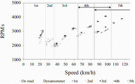
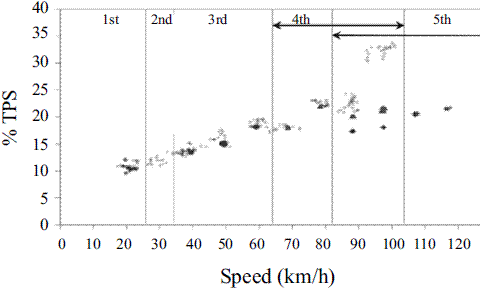
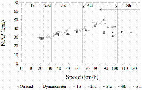
The loads imposed to the engine during the on road tests were reproduced on the chassis dynamometer according to the values reported in table 5. Figure 2 shows the results obtained for the case of NOx mass emissions and compare them with the ones obtained during the on road tests. As expected, figure 2 shows that the dispersion of the data obtained during the tests made on the chassis dynamometer are much smaller than for the case of the on road tests since laboratory test are less exposed to uncontrollable external variables that the ones presented during on road test. Figure 2 also shows that mass emissions obtained on the chassis dynometer are the same as the ones obtained during the on road tests for speeds lower than 90 Km/hr. Therefore it can be concluded that for this range of speeds, the emissions of the vehicle, at constant speed, can be reproduced on a chassis dynamometer. However it is also observed that for speeds greater than 90 Km/hr the mass emissions obtained on the dynamometer are smaller than the ones obtained during the on road tests. This can be due to differences in the load imposed to the engine. Figures 3 to 5 show the values reported by the RPM, TPS, MAP sensors for both type of tests.
Figures 3 to 5 show that in effect for speeds greater than 90 Km/hr the load imposed to the engine was smaller for the case of the laboratory tests. This difference could be due to the difficulties of the laboratory tests in simulating the effects of the air flow around the vehicle at its normal on road operation. Work is underway to find alternatives of reproducing the mass emissions of the vehicle on a chassis dynamometer under steady state conditions for speeds greater than 90 Km/hr.
ASM tests
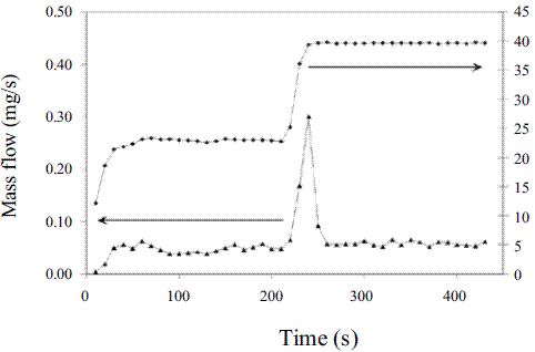
To explore alternatives to predict the pollutant emissions starting from the information gathered in the inspection centers, several ASM 5015 test were conducted on the testing vehicle. Figure 6 shows the typical results obtained for the case of NOx in terms of mass flow.
Figure 3 Comparison of the RPM measured during the constant speed tests on road and on the chassis dynamometer
Figure 4 Comparison of the % TPS measured during the constant speed tests on road and on the chassis dynamometer
Figure 5 Comparison of the MAP measured during the constant speed tests on road and on the chassis dynamometer
Figure 6 NOx mass emission during an ASM 5015 test
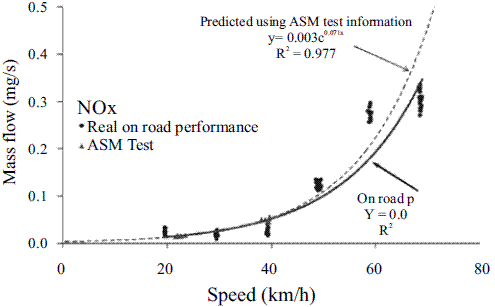
Figure 7 Exponential functions to predict NOx mass emissions at constant speed from on road tests and from ASM tests
Figure 6 shows that this standard test includes three steady state conditions: idle, 24 km/hr and 40 Km/hr. It also shows that the test protocol allows enough time between changes of speeds for the mass emissions to reach their steady state conditions. On the other hand, figure 7 shows that the mass emissions obtained during this type of tests are similar to the emissions observed during the on road tests. Therefore it is concluded that the ASM test can be used to predict the pollutant emissions of the vehicles when they move at constant speed. Furthermore it can be used to obtain up to a three degree of freedom function to predict pollutant emissions over the whole range of working speeds. Using the R2 criteria, exponential and quadratic functions were evaluated. For the NOx mass emission case a exponential function showed to best fit the experimental data obtained during the on road tests. Figure 2 shows the exponential function obtained. The same type of function was used to fit the data obtained with the ASM tests. Figure 7 compares these two curves. Figure 7 shows that the function obtained for the ASM tests predict well the on road mass emissions, especially at lower speeds. This demonstrates that the information gathered in the vehicular emissions verification centers can be used to estimate the emissions of each vehicle at any speed under steady state conditions. However the error of the predicting function increases as speed increases. This error can be reduced changing the ASM protocol test to include a third steady state condition around 75 Km/hr.
Conclusions
This paper describes a methodology to improve the accuracy of the vehicular emissions inventories developed in large urban cities based in the information gathered in the vehicular emissions verification centers during the execution of the inspection and maintenance program (I/M programs) implemented by the environmental authorities of the city. The methodology consists of approximating the typical driving cycle of the city in segments of constant speed and constant acceleration (operational modes). The total mass of pollutants emitted by a vehicle during the driving cycle is the sum of the mass emitted during each segment. This methodology assumes that there exist functions that predict the mass emissions of pollutants as function of speed and acceleration for each type of vehicle. It also assumes that 100% of the vehicular fleet is evaluated using ASM 5015, ASM 2525 or similar type of tests during the execution of the I/M programs and that those type of tests provide enough information to obtain the exact mass emission functions for each particular vehicle.
Experimental work on road and on chassis dynamometer was developed to explore the feasibility of implementing such methodology for the case of the constant speed mode of operation in a particular type of car. Results show that the mass of pollutant emitted increases with the speed of the vehicle and that an exponential function fit well (R2>0.97) the experimental data obtained during on road tests at constant speed. It was also found that, for speeds lower than 90 km/h, tests on a standard chassis dynamometer under steady state conditions reproduce the performance of the vehicle in terms of the mass of pollutant emitted on road at constant speed. At higher speeds the effect of the drag force on the vehicle becomes important and therefore the test on dynamometer cannot reproduce the operational conditions on the engine when the vehicle moves at constant speed on road. Finally, it was found that the exponential function to estimate mass emissions of pollutants, obtained from the ASM type of tests, predict well (R2>0.84) the performance of the vehicle when it moves at constant speed on road. This demonstrates that the information gathered in the vehicular emissions verification centers can be used to estimate the emissions of each vehicle at any speed under steady state conditions.
Work is underway to reproduce the work reported in the present document on a sample of light duty vehicles looking for demonstrating the validity of the present conclusions to the general case of this segment of vehicles.
References
1. B. Onursal, S. Gautam. Contaminación Atmosférica por Vehículos Automotores. Experiencias recogidas en siete centros urbanos de América Latina. Banco Mundial. USA. 1997. pp. 1-337. [ Links ]
2. Secretaría de Medio Ambiente y Recursos Naturales. Segundo Informe de la situación del medio ambiente en México. Compendio de Estadísticas Ambientales 2005. México 2005. http//app1.semarnat.gob.mx/ dgeis/informe04/09planeacion lindexplaneaction.html. Consultada el 22 de octubre de 2008. [ Links ]
3. Environmental Protection Agency and Sierra Research Inc. MOBILE6 On-Road Motor Vehicle Emissions Model. 2001. pp. 1-261. [ Links ]
4. H. Rakha, K. Ahn, A.Trani Comparison of MOBILE5a, MOBILE6, VT-MICRO, and CMEM Models for Estimating Hot-stabilized Light Duty Gasoline Vehicle Emissions. Canadian Journal of Civil Engineering. Vol. 30. 2003. pp. 1010-1021. [ Links ]
5. P. Degobert, Automobiles and Pollution. Society of automotive engineers. Ed. Technip. París. France. 1995. pp. 1-70. [ Links ]
6. Norma Oficial Mexicana NMX-011-1993-SCF Método de Prueba para la Evaluación de Emisiones de Gases del Escape de los Vehículos Automotores Nuevos en Planta que usan Gasolina como Combustible. México. 1999. pp. 1-4. [ Links ]
7. J. I. Huertas, A.Valdez. Desarrollo de Ciclos Típicos de Conducción para el Municipio de Naucalpan. V Simposio de Contaminación Atmosférica. México. Agosto 2005. pp. 1-50. [ Links ]
8. E. Booth, T. Muneer, J. Kubie, H. Kirby. A Review of Vehicular Emission Model and Driving Cycles. Proceedings of the Institution of Mechanical Engineers. Professional Engineering Publishing. Scotland (UK). 2002. pp. 777-797. [ Links ]
9. M. Andre. Driving Cycle Development Characterization of the Methods. SAE International spring fuels and lubricants meeting. USA. 1996. [ Links ]
10. http://www.nissanplatina.com.mx. Consultada el 24 de agosto de 2007. [ Links ]
11. http://www.pemex.com/ México. Consultada el 25 de octubre de 2007. [ Links ]
12. http://www.sma.df.gob.mx México. Consultada el 10 de septiembre de 2007. [ Links ]
13. H. Frey, A. Unal, N. Rouphail, J. Colyar. On-road Measurement of Vehicle Tailpipe Emissions Using a Portable Instrument. Journal of the Air & Waste Management Association. Vol. 53. 2003. pp. 992- 1002. [ Links ]
14. J. I. Huertas, E. García, J. Díaz Development of a Fifth Wheel to Evaluate the Performance of Vehicles by on Road Tests. CARS & FOF 2004. Vol. 20. 2004. pp. 205-212. [ Links ]
15. J. B. Heywood. Internal Combustion Engine Fundamentals. Ed. Mc. Graw Hill Science Engineering. Cambridge (UK). 1988. pp. 9-930. [ Links ]
(Recibido el 20 de febrero de 2009. Aceptado el 25 de agosto de 2009)
*Autor de correspondencia: teléfono: +52 + 722 + 279 99 90, ext. 2113, fax: + 52 + 722 + 274 11 78. correo electrónico: jhuertas@itesm. mx (J. Huertas).


